Renault Twingo 1 compatible products - Independent shop
Tightening torques
To ensure the safety and longevity of your vehicle, following manufacturer recommendations using a torque wrench is an essential step in every repair.
What is a tightening torque?
In automotive mechanics, tightening torque refers to the rotational force applied to a screw or nut to optimally assemble parts. Expressed in Newton-meters (N·m), it should never be left to chance.
Tightening torques too low and the part may loosen due to vibrations, leading to breakdowns or serious accidents.
Excessive tightening torque can stretch the thread, deform components (like a cylinder head) or snap the screw clean off.
In the absence of torque specifications provided by the manufacturer, it is sometimes necessary to apply the standard torque values according to the type and diameter of the bolt. The following table lists the most common reference values for ISO metric bolts, standard thread, in classes 8.8 and 10.9.
Noticed : The values are indicative. For critical assemblies (safety, engines, structures), use the manufacturer's data or the applicable ISO/UNI standard. Lubrication, nut type, engagement depth, and surface roughness strongly influence the required torque.
Bolt diameter
Class 8.8 (dry)
Class 10.9 (dry)
M4
0,3
0,4
M5
0,6
0,9
M6
1
1,5
M8
2,5
3,6
M10
4,9
7,2
M12
8,5
12,5
M14
13,5
20
M16
21
31
M18
28
40
M20
40
57
Expressed in m.kg.
All torque specifications for the Renault Twingo 1
Engine
ITEM
TORQUE (m.kg)
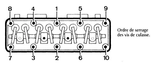
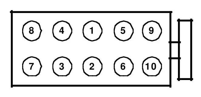
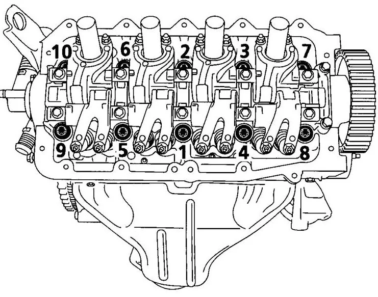
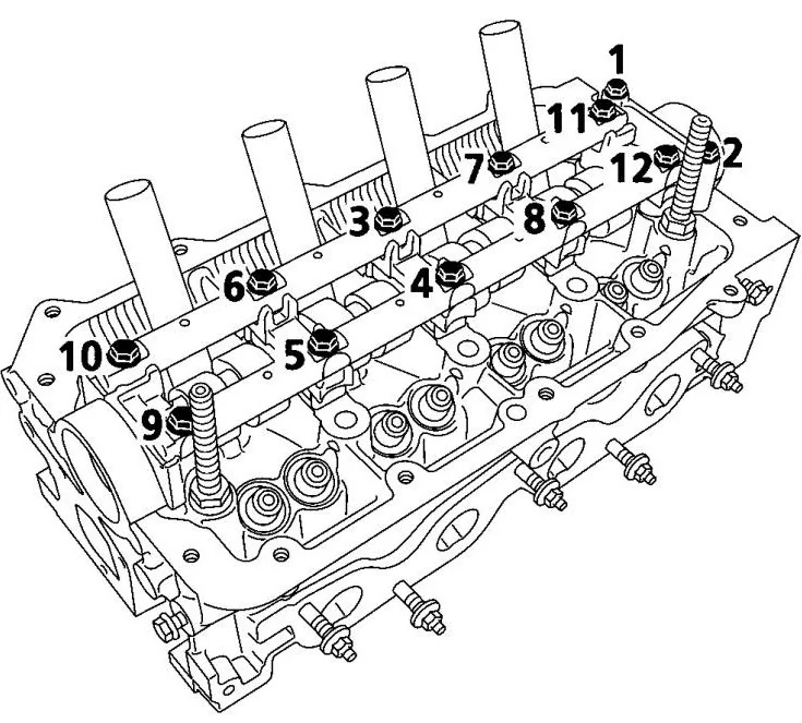
Cylinder head bolts (threads and underside of head oiled) – 1st phase, according to tightening order
Completely loosen screw 3, then tighten to 0.7 and angle tighten to 50° +/- 6°. Repeat this operation for screws 4 to 12, in order.
Oil pump
0,9
Water pump
0,9
Flywheel bolt
1.8 then angular tightening of 110° +/- 6°
Lower crankcase screw on engine block
1
Lower crankcase screw on clutch bell
4
Camshaft sprocket screw
3. Then, apply angular tightening of 45° +/- 6°
Crankshaft pulley bolt
4. Then, apply angular tightening of 70° +/- 6°
Timing belt tensioner pulley
2,4
Exhaust manifold mounting nut
2,5
Intake manifold mounting screws
Hand tightening, then pressing to 0.6, and final tightening to 1
Cylinder head cover screws
1,2
Spark plugs
3 then angular tightening at 45° +/-6°
Right engine mount fixings
6,2
Securing the lower engine mount to the cradle
6,2
Attaching the lower engine mount to the gearbox casing
11
Mounting the left gearbox bracket to the chassis
2,1
Attaching the left-hand bracket to the gearbox
6,2
Clutch
ITEM
TORQUE (m.kg)
Mechanism fixing screw
2,5
Flywheel mounting bolts
5
Gearbox on engine
5
Transmission
ITEM
TORQUE (m.kg)
Gearbox on engine
5
Drain plug
1,8
Filling/level cap
0,15
Left transmission boot fixing screw
2,5
5th gear crankcase screw
2,5
Gearbox housing half-case assembly screws
2,5
Reverse gear switch plug
2,5
Difficult point in 5th grade
1,9
Primary shaft nut
13.5 with Loctite Frenbloc
Secondary shaft screw
8 with Loctite Frenbloc
ITEM
TORQUE (m.kg)
Securing the oil strainer
0,9
Hydraulic distributor mounting screw
0,9
lower crankcase screw
0,9
Converter drive sheet metal screw
2,5
Automatic transmission retaining lathe screw
4
Automatic transmission support screw on elastic buffer
5,5
Oil cooler screw
4
ITEM
TORQUE (m.kg)
Left transmission boot on gearbox
2,5
Gearboxes on engine
4,5
Secondary shaft screw
7
Primary shaft nut
19
Clutch housing on gear housing
2,5
Rear cover on gear housing
2,5
Drain plug
2,5
Reverse light switch
2,5
M6 screw of the pump
1
M8 pump screw
2,4
M10 pump fixing screw
4,4
Hydraulic control block nut
2,1
Hydraulic control block stud
0,8
High-pressure hose connection
1,4
Accumulator
4
ITEM
TORQUE (m.kg)
Transmission nut
25
Left-hand gearbox boot fixing screw
2,5
Wheel screws
9
Direction
ITEM
TORQUE (m.kg)
Screws for attaching the housing to the cradle
5
Ball joints on pivot
3,5
Axial ball joints on rack and pinion
5
Ball joint clamping screws on tie rods
2
Steering column universal joint clamping screw
2,5
Steering wheel nut
4
Steering column mounting screw
2,5
Wheel screws
9
Suspension
ITEM
TORQUE (m.kg)
Shock absorber rod nut
6
Pivoting strut
11 (nut facing backwards)
Ball joint on wishbone
7,5
Ball joint tail clamping screw on pivot
6
wishbone pivot bolt on cradle
11,5
universal joint nut
25
Steering ball joint on pivot
3,5
Cradle on a crate
6,5
Wheel screws
9
ITEM
TORQUE (m.kg)
Upper shock absorber mounting screw
1,5
Lower shock absorber mounting screw
7
Shock absorber rod nut
2,2
Rocket mounting screw
4
Axle body fixing screws to the clevises
5
Screws for fixing the brackets to the body
4
Hub nut
17
Wheel screws
9
Braking
ITEM
TORQUE (m.kg)
caliper guide pin screw
10
Disc mounting screw
2
Pipes on master cylinder
1,3
Pipe on bracket
1,5
Pipe on rear receiver cylinder
1,3
Bleed screw
0.4 to 0.8
Rear brake flange and spindle
4
Brake booster mounting nuts
2,3
Master cylinder fixing nuts
1,3
Securing the hydraulic unit to the support
0,8
Wheel screws
9
Source : Renault documentation.
Manage consent
To provide the best experience, we use technologies such as cookies to store and/or access device information. Consenting to these technologies will allow us to process data such as browsing behavior or unique identifiers on this site. Not consenting or withdrawing consent may negatively affect certain features and functions.
Functional
Always active
Technical access or storage is strictly necessary for the legitimate interest purpose of enabling the use of a specific service explicitly requested by the subscriber or user, or for the sole purpose of carrying out the transmission of a communication over an electronic communications network.
Preferences
Technical access or storage is necessary for the legitimate interest purpose of storing preferences that are not requested by the subscriber or internet user.
Statistics
Storage or technical access that is used exclusively for statistical purposes.The storage or technical access is used exclusively for anonymous statistical purposes. In the absence of a subpoena, voluntary compliance from your internet service provider, or additional records from a third party, the information stored or retrieved for this sole purpose generally cannot be used to identify you.
Marketing
Technical access or storage is necessary to create user profiles in order to send advertisements, or to track the user on one or more websites with similar marketing purposes.